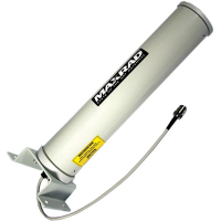
2.4 GHz Yagi Antennas
A2410NJ-DY, A2415NJ-DY
Notice: A2415NJ-DY has reached "Discontinued" status.
Typically, Yagi antennas compose an array of linear elements, parallel to one another and attached perpendicular to and along the length of a metal boom. Elements on one side of the feed element are longer and act as reflectors. Elements on the other side of the feed element are shorter and act as directors. The antenna radiates in a beam out the end with the shorter elements. Beamwidth varies (longer length produces a narrower beam). This type of antenna produces gain in the 6 to 15 dBi range depending on the overall geometry of the antenna.
Features and Benefits
- Field adjustable to allow vertical or horizontal polarity. Eliminates co-channel interference from neighboring radiators. Polarity markings molded on the antenna ensure proper installation and correct orientation
- Optional articulating mount allows precise adjustment of the antenna both vertically and horizontally
- All antennas include a robust mast mount bracket designed to withstand 125 mph wind
- Matched principal plane beamwidths with excellent sidelobe suppression and cross polarization rejection of more than 20 dB. Provides superior signal quality with enhanced gain performance and minimal interference from neighboring radiators
- 30 dB front-to-back ratio permits less physical separation on the tower, thus adding mounting flexibility at installation sites where space is limited
- Attractive weather-proof radome constructed of UV resistant material provides robust and trouble free use in harsh outdoor climates
All antennas have been tested for compatibility with RadioLinx products. Please see our Antenna Selection Guide to assist you in choosing the best antenna for your application.
Applications
All antennas have been tested for compatibility with RadioLinx products. Please see our Antenna Selection Guide to assist you in choosing the best antenna for your application.
Specifications
| Radom Material |
White plastic |
| Polarization |
Vertical or horizontal, linear (user adjustable) |
| Lightning Protection |
DC grounded |
| Nominal Impedance |
50 Ohms |
| Mounting Method |
Heavy duty Yagi mounting bracket (included) permits mast mounting on mast up to 2 inches O.D. RLX-MYK18 adjustable wall/pipe mount allows 180° (included angle) azimuth and elevation adjustment (sold separately) |
| Termination |
Type N jack standard with all models |
Hardware
Electrical Specifications
| Product # |
FrequencyRange |
Gain |
Front-to-Back Ratio |
Horizontal Bandwidth |
Vertical Beamwidth |
VSWR |
| A2410NJ-DY |
2.4-2.5 GHz |
10 dBi |
23 dB |
55° |
55° |
<1.5:1 |
| A2415NJ-DY |
2.4-2.5 GHz |
15 dBi |
30 dB |
30° |
30° |
<1.5:1 |
Downloads
| 2.4 GHz Directional Yagi Antenna Datasheet | 132.10 kB | Last Modified 12/14/2009 |


